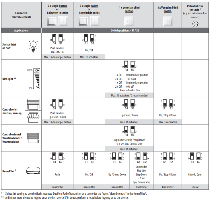
The position of the DIP switches depends on the connected switching element. The correct switch position of the UP radio transmitter can be taken from the table.
Important: Before logging on, note which mode the transmitter is in. This determines which command is sent and with which pushbutton or switch the transmitter is operated.
Example 1: Roller shutter actuator is controlled with UP and DOWN and a switch is connected. Dip S1 is set to 0 and Dip S2 to 0.
Example 2: Universal actuator is controlled with ON/OFF for channel 1 and 2 and a serial pushbutton is connected. Dip S1 is selected to 1 and Dip S2 is selected to 1. When logging on, it must be specified which button is for which channel.
Example 3: Two tubular motor actuators are to be controlled in the sequence Open/Stop/Close/Stop. A series button is connected. Dip S1 to 1 Dip S2 to 1 is selected. When registering, it must be determined which key is for which actuator.